Introducing a Blackmagic Camera Control System with Arduino, ThinClient, and Custom Frontend

Control Blackmagic Cameras with an Arduino, ThinClient, and Custom Frontend Easily control your Blackmagic cameras with a unique combination of an Arduino Uno, a Fujitsu Futro S920 ThinClient, and a custom Angular frontend application.

The Idea

The Idea Blackmagic cameras are known for their high-quality video and versatility, but controlling them can sometimes be a bit cumbersome. While Blackmagic provides an SDK board for an Arduino Uno to help control their cameras, there’s still room for improvement in terms of user experience and ease of use.

I created a solution for a complete camera control system using an Arduino Uno with the Blackmagic 3G‑SDI Shield for Arduino, a Fujitsu Futro S920 ThinClient, and a custom Angular frontend application. This setup allows for convenient control of your Blackmagic cameras, whether you have one or multiple cameras in your setup.

The Hardware

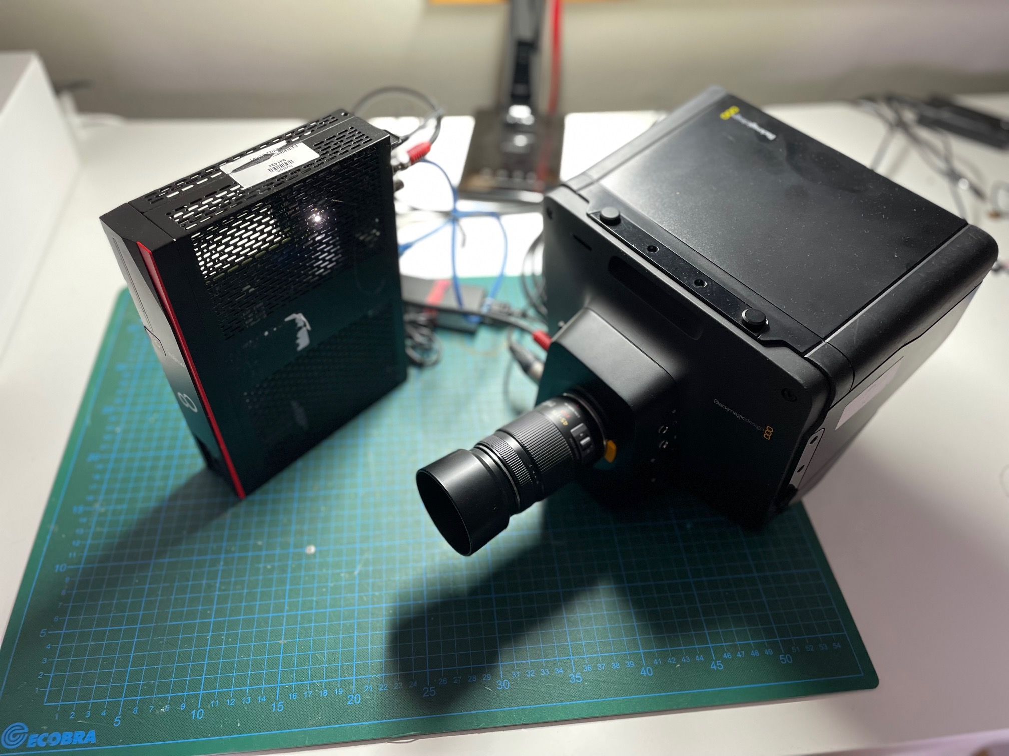
The setup consists of three main components:

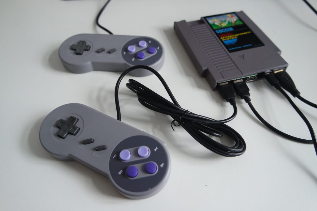
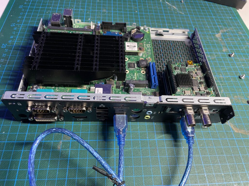
  1. Arduino Uno with the Blackmagic 3G‑SDI Shield for Arduino: The Arduino Uno is connected to the Fujitsu Futro S920 ThinClient via USB and has the Blackmagic SDK board mounted on top of it. The Arduino runs a custom sketch that receives commands via serial communication and translates them into commands available in the sdk library provided by Blackmagic.
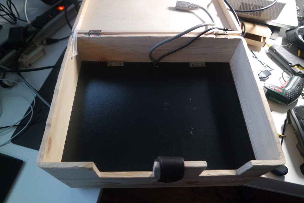
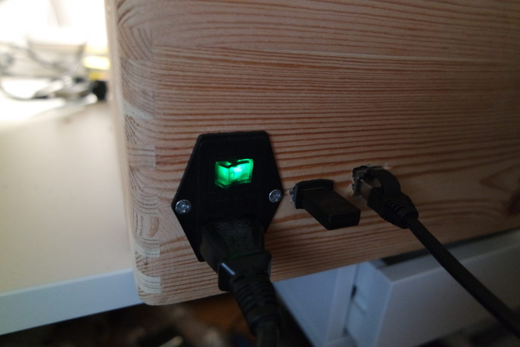
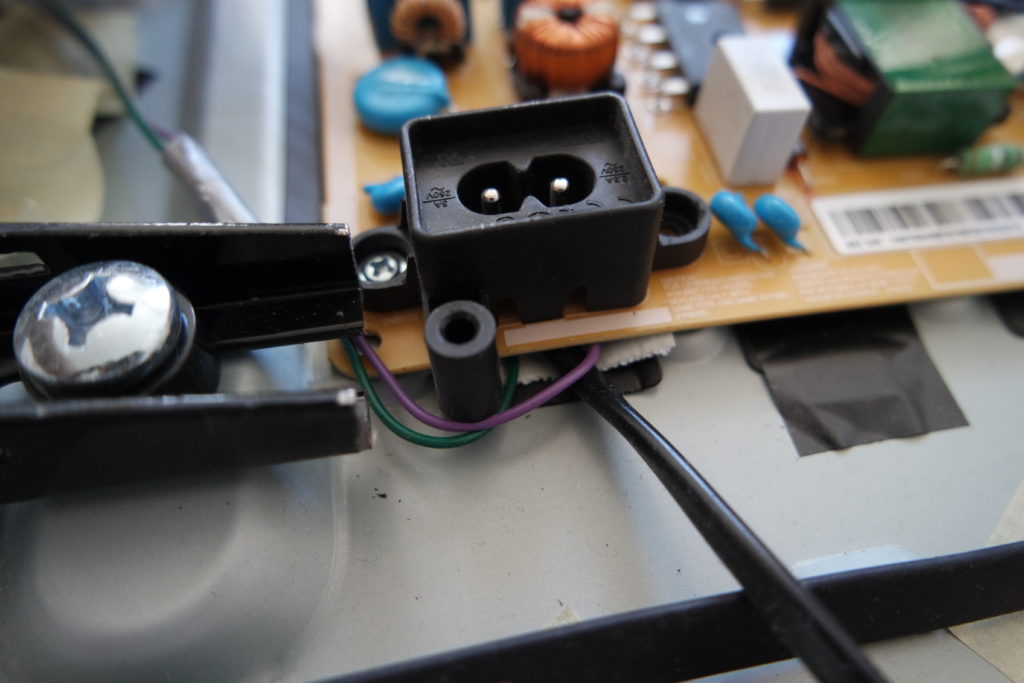
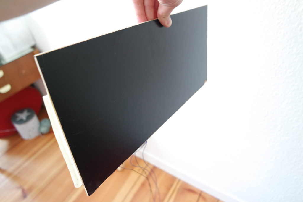
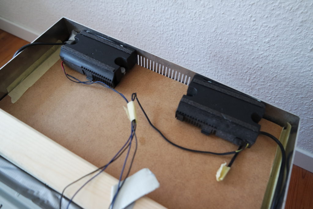
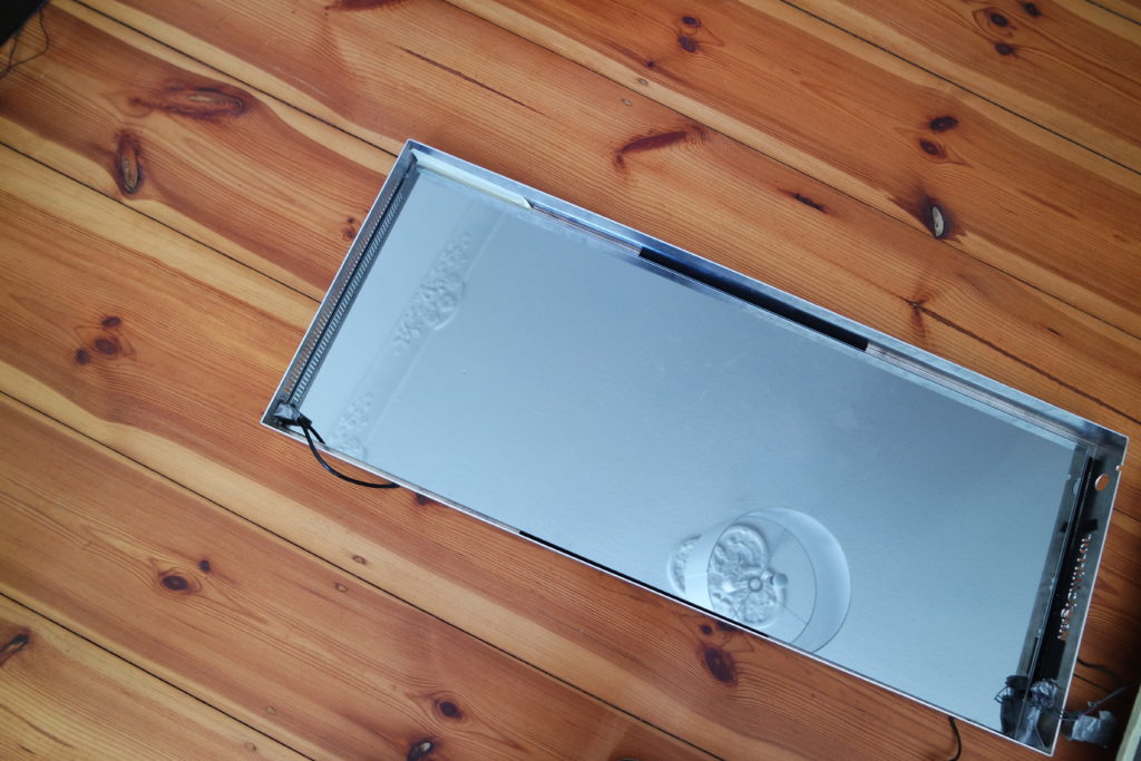
  2. Fujitsu Futro S920 ThinClient: This compact computer features 8GB DDR3 RAM and a 128GB SSD, providing enough power to run the backend and frontend software components. It also houses the Arduino Uno with the Blackmagic SDK board inside its case. The ThinClient runs a lite version of Ubuntu (Ubuntu MATE) and hosts the backend and frontend software components, as well as the tally listener.
  3. Blackmagic Camera(s): Any Blackmagic camera that supports SDI control can be used with this system. We have tested it with Blackmagic Studio Cameras.

The Software

The software solution consists of several components:

  1. Arduino Sketch: A custom sketch, Commandparser.ino, receives commands via serial communication (USB port) and translates them to the commands available in the BMDSDIControl.h library provided by Blackmagic.
  2. Backend: A Python FastAPI HTTP server with several endpoints to control the cameras and manage their configurations. The backend can be started by running main.py, and the available endpoints can be found in the postman collection. The configuration of the available cameras and their corresponding names are stored in the config.yaml file.
  3. Tally Listener: A Python script that connects to a vMix software via TCP to subscribe to changes in the current tally light and sends the changes to the backend. The tally listener can be started by running main.py and configured in the config.yaml file.
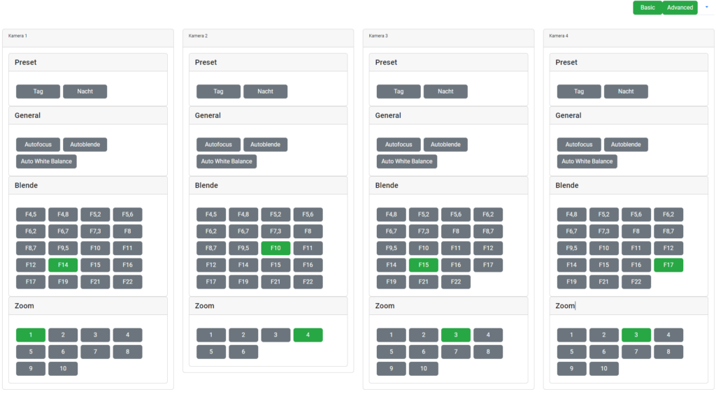
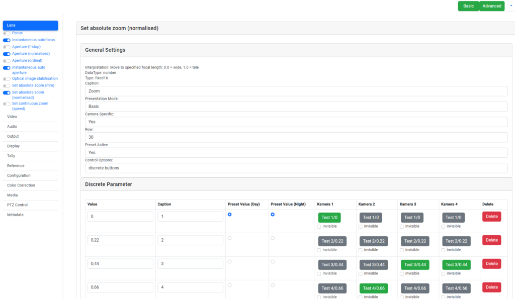
  4. Frontend: An Angular application that visualizes the structured data from the backend’s “/groups” endpoint, allowing users to configure and control the cameras using a web-based interface. The frontend can be started by running ‘

Get Started

To set up and control your Blackmagic cameras using our solution, follow the steps in the GitHub repository. Once everything is up and running, you’ll have a powerful and easy-to-use camera control system at your fingertips.

Whether you’re a professional videographer or just someone who wants more control over their Blackmagic cameras, this unique combination of hardware and software is a game-changer. So get ready to take your camera control to the next level!

Bluetooth Buttons

Control your Sonos speakers with Bluetooth Buttons

Here is the ideal solution to control your SONOS speakers using cheap Bluetooth Buttons, originally build to interact with your phone while driving.

The Idea

I’m pretty sure, you have heard of SONOS. They sell a wireless a Home Sound System based on high quality speakers. The Speakers are usually controlled by an app. Once you have chosen your song of choice interacting is also possible with buttons on the top of each speaker.

Well, rumors are telling an upcoming integration of voice recognition and assistance. This should make it easier to interact with your music system using your voice. An very useful feature which is totally necessary to compete and survive in times of fast evolving home assistants.

In my case I was looking for a simple and fast solution to interact with the speakers from any location in my house without always unlocking the phone, starting up the app and waiting its initialization. I was inspired by the hacks of amazons dash button, but I needed to find a solution for sending more than one command. So the ideal solution are Bluetooth Buttons, originally build to interact with your phone while driving. And hey, compared to voice control this is even easier, faster and much more noiseless (as long as you button is in reach).

The Hardware

Here is how my setup is working:

  • A Raspberry Pi 3 Model B is listening to the paired and connected buttons.
  • Once the paired Bluetooth button sends a command to the Pi, it’s forwarded to an HTTP based API controlling the SONOS Speakers.

I tested this with several buttons, as long as the button is delectable with any other Bluetooth device everything worked as expected. Here are three tested and used for some month:

The Script

As usual you can find the python based script on GitHub.

After following the installation instructions, all you need to adjust are variables in the header of the script.

# Modify your variable here
roomname = "Kitchen" # roomname your Sonos Speaker is located
buttonname = "Satechi Media Button" # also tested with "BT-005"
host = "localhost" # when installed on the same host use localhost
port = "5005" #default 5005
key2commandPairs = {"KEY_PLAYPAUSE":"playpause",  # edit your button:command pairs
                    "KEY_NEXTSONG":"next",
                    "KEY_PREVIOUSSONG":"previous",
                    "KEY_VOLUMEUP":"volume/+2",
                    "KEY_VOLUMEDOWN":"volume/-2"}
# -------------------------------------------------


Time to play some loud good music. Enjoy!

Building a retro console in a NES Cartridge using a Raspberry Pi Zero

This idea is so brilliant. Building a retro console using a Pi Zero and housing everything in these old school catridge from a NES console.
Here you will find the tutorial, which is written, very well. I just wanted to share the version I made and give a little summary of the parts I’ve used.

Against the recommendation it the linked tutorial I decided to keep the diode from the USB hub and drilled a tiny little hole in the case.
Now, this little indicator shows, if power is connected to the cartridge.

Using RetroPie as a emulator is a well know and easy to use software for this kind of beautiful hardware.

Time to play some of the good old games using the mobile projector box. This is a real dream team!

Building a mobile projector box – The Summary

The Summary

A safe and mobile casing for the old projector was needed. It’s capable of streaming any media from another device using the steam hard- and software. All you need is a power socket and a white wall. Optional Ethernet input and audio output included.

What did it cost?

Besides the Projector and the Steam Link which were already there. The box and the HDMI sound separator were the most expensive. But see on you own.

Box 22,95 €
HDMI sound separator 15,99 €
audio jack recessed socket 12,50 €
Ethernet recessed socket 11,24 €
USB Power supply 7,00 €
Cinch to jack adapter 6,99 €
Power supply recessed socket 6,69 €
HDMI cable short 5,48 €
Ethernet cable short 4,85 €
Hinges 2,00 €
Total 95,69 €

How long did it take?

Prototype not included this needed about 40 hours. Most challenging was to cut the housing. First it needed to be shortened, than the holes fort the interfaces were needed.
If you have everything in place this could be put together in less than a half hour.

What’s next?

Let the Box hover over the ground and control it with your voice?! Well, first things first. Now it’s time for a movie!

Building a mobile projector box – The housing and the inner parts

The Box needed to enclosure the dimensions of the projector and had to fit under the bed frame. Not that easy.

In the end I ordered a higher box, and made a large cut to reduce their height by 2.5 cm.

With a nice equipment gaming PC next door, I tried to stream games to the projector via a Steam Link. This worked quite well as long as it was connected via Ethernet.
Another challenge was the sound output. The Steam Link only provides audio output via HDMI.

Even the projector was capable of playing sound, this was no fun. Only noise.

Unfortunately, the projector did not provide a way to output the sound. So I needed to split the sound from the HDMI signal before it went to the projector.

Cables over cables, this needed to be ordered.

Everything  stored in the lower part.

Interfaces. Power socket, two USB and Ethernet and audio output.

Angle adjustment is possible with a variable belt flap.

Building a mobile projector box – the summary

Building a mobile projector box – The Idea

The Idea

To watch movies from time to time on a canvas is the most comfortable position, I decided to place the projector right under my bed. In case it’s not used I would just slip it under the bed frame.

An easy solution was found by using a cardboard box, but  after some days a more orderly and safer solution was needed. So I decided to build a nice casing, which collects the cables and protects the projector.

It stated out the following features were useful:

  • low height of the case, capable to be stored under the bed (max height 21 cm)
  • two areas with the case (top and bottom), to hide the cables under to projector
  • adjustable horizontal angle of the projector
  • dust proof storage, if not in use
  • optional: sockets for power and Ethernet

See here the creation of the housing with several interfaces…

Building a big MagicMirror with metal frame – The summary, part list and prices

This blog shows the costs, used parts and summarizes the main challenges I experienced when building my smart mirror.

The Summary

When I first run into the MagicMirror project I was convinced this was something I wanted to build on my own.  Without the amazing work and the easy to use framework by Michael Teeuw, this wouldn’t any possible to archive. And this was real fun!

What did it cost?

It total I spend exactly 737,70 € on this project. Much more than I was expecting in the beginning. As already told, most expensive was the TV Screen. But see yourself…

Items Object Model Price
1 Frame custom 100,00 €
1 Mirror custom 110,00 €
1 Screen Samsung UE32J6250SU 32 Full HD Smart TV Wifi Black 354,89 €
1 Mount Hama Fix Ultraslim TV Wall Mount Medium Black 14,99 €
1 RaspberryPi3 Raspberry PI 3 Model B A1.2GHz 64-bit quad-core ARMv8 CPU, 1GB RAM 37,93 €
1 RaspiCase SB Components Raspberry Pi 3 Transparent Case 6,49 €
1 Camera Raspberry Pi camera module NoIR V2 36,90 €
1 Power Supply Rydges EU 5V 3A Micro USB Power Supply 9,99 €
1 Short HDMI cable 0,2m SunshineTronic High Speed HDMI cable with ethernet 6,90 €
40 Infrared LEDs Infrared OSRAM LEDs SFH 485 15,00 €
40 LED reflector 5mm Reflector 5mm 21,21 €
2  Power socket Euro8 9,50 €
1 Power cable white Euro8 Maxima Trade Netzkabel 8,90 €
1 Wires, Screws, woodbars several 5,00 €
Total 737,70 

How long did it take?

It’s hard to say how much time I had spent only on the hardware. I started to dive in the code very early. Maybe 60 to 80 hours including researches regarding the setup and hardware.

What did I learn?

As already told I underestimated the price. But the real challenge in this project was to improve the pictures made with the camera, behind the mirror glass.
Several prototypes of the IR spotlights where built, I had to spend several hours of adjusting parameters and retaking sample pictures for the face recognition module to get it work properly.

After a few month, the number and of modules I’d like use on the mirror started raised. So did the requirements on CPU and memory resources. It turned out the Raspberry Pi 3 quickly reaches its limits, when using modules for face or speech recognition or when displaying a rotating globe. So right now, I’m already thinking about how to rebuild the inner parts to get a board with more power.

What’s next?


The possibilities of the Magic Mirror are immense. Now I have this cool piece of data provider right in my hall it’s time to make this a impressive info board. Therefore several modules are easily to add to the open source software framework. Several developers made some amazing software. So did I.
If you’re interested, check out my developed modules for the Magic Mirror.


Building a big MagicMirror with metal frame – The Assembling

The Assembling

1Time to put everything together. Or with other words let’s say: ‘Grab the duct tape, we’re building a magic mirror’.


First a little soldering was needed, to power up the TV screen without using the normal power cable for space reasons.


At the bottom of the TV screen a black cardboard prevent any light coming through the mirror. So for person standing right in front of the mirror, also the lower part just looks like a normal mirror.

Behind the cardboard the TV Speakers were taped to provide a nice sound if needed.


The Power were already installed and the mirror fits as expected.

The wooden bars which are fixing the frame and mirror to the TV Screen are screwed to the frame.

A proper mount its holding everything tight.

Final installation hanging save on the mount.

Building a Magic mirror – The Summary

Building a big MagicMirror with metal frame – The Camera

The Camera

One of the first modules for the magicmirror framework I had to try myself, was the face-recognition module by paviro. After experimenting some time with the software I was fully convinced. The Mirror needed a camera.

For keeping the ‘magic’ in the mirror, It’s was not an option to mount the camera outside the frame. A grave and not so easy decision as stated out during the further tests.

The mirrors final location is in the windowless doorway. Most of the time no natural lighting helps the camera to make sharp and contrast shots. Maybe an IR version of the raspi camera module could do this tough job? Yes it can, but of course …. it needs infrared light.

Light – even infrared of course – get partially reflected by the two way mirror. Surprise.
So to get the same brightness for a camera behind the mirror you need more like 60 % ‘more’ light than camera outside would need.

But obviously every light emitted by a lamp behind the mirror suffers from the same effect in brightness.

This wasn’t unsolvable, but as I was totally convinced everything had to find its place within the frame it was a tough lesson I had to learn.

With a thin mirror as planned – and a frame already ordered – there was no way integrating a custom infrared spotlight within the mirror. So I decided to try my luck with infrared LED. And hey, why not reflect the light, which was reflected by the mirror again.

So first attempts were made using aluminium foil as ‘re-reflector’. Better but far away from a good image in a near dark environment.

Finally I decided to maximize the number of LEDs with an overall voltage consumption of nearly 12V by two matrices of 3 X 6 spots around the camera. Each LED has a reflector itself to focus in the forward direction.

As the camera is mounted on top of the screen, lights and camera are positioned in an angle of 45° to capture the face of the person viewing in the mirror.

Very helpful for positioning and lights in this position was a acryl mirror behind the led, with an right angled outside part.

The camera itself is connected to the raspberry Pi and was mounted in the wooden bar which is fixing the frame on the monitor.

Finally was able to receive bright pictures which were usable for recognize persons behind the mirror.
Time to start the real fun part: The Assembling

Building a big MagicMirror with metal frame – The Frame

The Frame

With the decision regarding screen  and mirror  taken final dimensions were clear and the fun with constructing a frame could begin. To get a thin product with a solid and industrial look I wanted to use a bent enclosure out of sheet metal.

With the kind help of my flatmate, who owns a hardware prototype company, we were able to design a nice prototype.

The results of the construction process were provided to a nearby metal factory. The design drawing is available for download.


The construction as Solidworks® Part is also available online on Onshape.

After waiting more than five very looong weeks, the frame was finally crafted and made me another 100€ poorer. Man, this was getting way more expensive than first calculated.
But every bad taste vanished when the parts were together for the very first time.

As the TV screen is mounted right to the wall, the frame should ‘sit’ on the screen, holding the glass of the mirror itself. To fix the frame properly to the screen, we first planned to use individual metal blocks on each edge of the screen and tighten them with two screws.

Small spoiler: In the end I decided to use two wooden bars on the top and the bottom of the mirror to fix the frame. There were much more easy to customize and gave an additional vertical stability to the frame.


On the top and the button of the frame a place for a power socket was planned. The speakers of the TV screen were easily to ease and found their new place on the button of the frame, able to play through several oval openings.

Soft tape from a ‘hook and loop tape’ is used on the inner side of the frame prevent the monitor screen from feared scratches.


Time to put every piece to its final destination – The Assembling